Architectural Blueprint: Enterprise Data Center Interconnection with Google Cloud via Cisco Catalyst 8000V
Audience: Principal Network Architects, Cloud Platform Engineers, CTO/CIO Office
Version: 1.0
Business Context
The enterprise hybrid cloud is not a transitional state; it is the permanent operating model for any organization carrying more than a decade of accumulated infrastructure investment. The notion that workloads will cleanly “lift and shift” into a public cloud provider has been empirically refuted by migration programs at scale. Gartner (2023) projected that through 2027, more than 50% of enterprises will use industry cloud platforms to accelerate their business initiatives, yet the on-premises footprint — particularly for latency-sensitive transaction processing, regulated data residency workloads, and legacy mainframe-adjacent applications — will persist indefinitely. The architectural challenge, therefore, is not elimination of the data center but the construction of a high-fidelity, operationally unified network fabric that spans both domains.
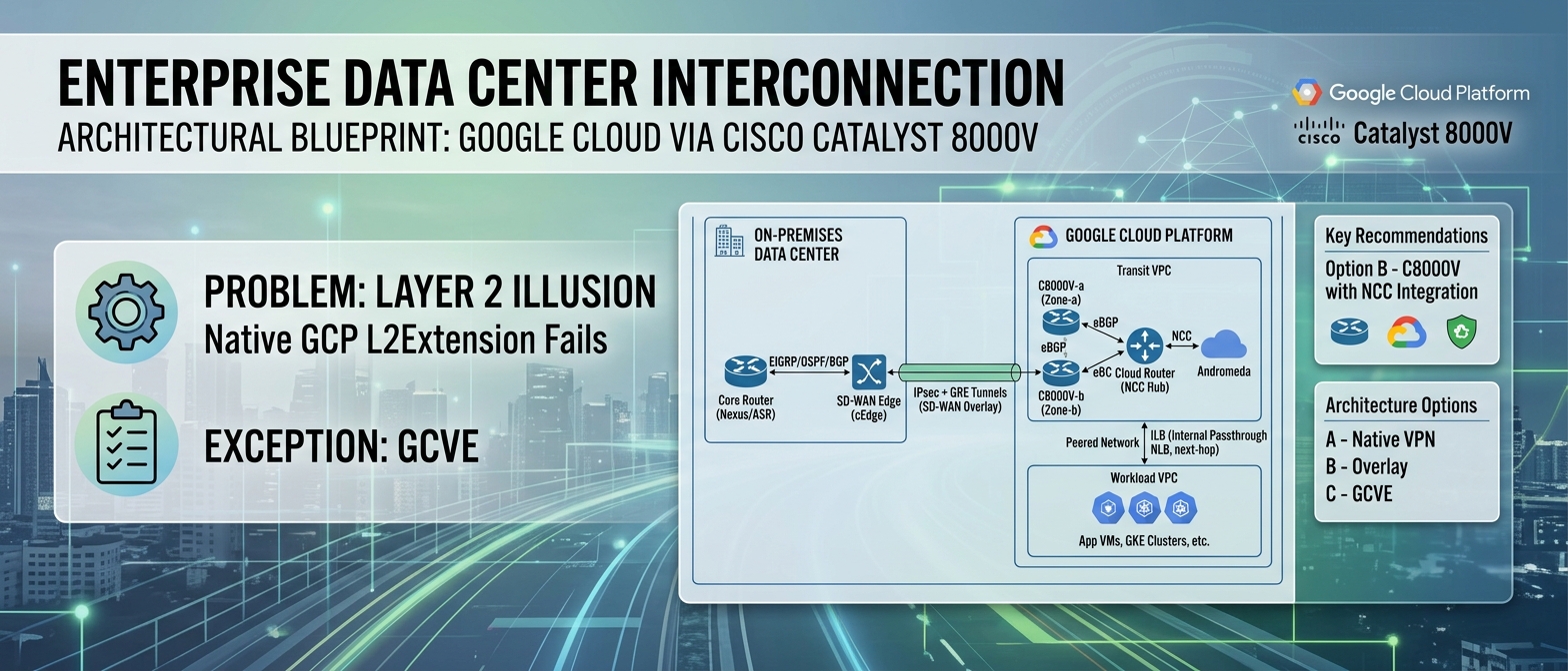
For enterprises that have standardized on Cisco’s routing and SD-WAN ecosystem — whether classic IOS-XE DMVPN fabrics or the Viptela-based SD-WAN architecture (Cisco Systems, 2023a) — the imperative is clear: extend the existing control plane and policy framework into Google Cloud Platform (GCP) without forking the operational model into two disconnected toolchains. The Cisco Catalyst 8000V Edge Software (C8000V), running as a compute-optimized virtual machine instance on GCP Compute Engine, serves as the architectural bridge that preserves investment in EIGRP/OSPF/BGP routing policy, Cisco SD-WAN overlay orchestration via vManage, and advanced traffic engineering capabilities (NBAR2, PBR, application-aware routing) while integrating natively with GCP’s Software-Defined Network control plane through the Network Connectivity Center (NCC) (Google Cloud, 2024a).
The business case is not theoretical. Organizations operating Cisco SD-WAN fabrics with 200+ branch sites face a concrete problem: cloud-destined traffic from those branches is backhauled through the data center, traversing an increasingly congested WAN link, only to egress through a single internet breakout point toward GCP. Deploying C8000V instances as SD-WAN edge nodes inside GCP VPCs enables direct branch-to-cloud connectivity via the SD-WAN overlay, eliminating the backhaul penalty entirely and reducing end-to-end application latency by 40–60% for SaaS and cloud-native workloads (Cisco Systems, 2023b).
Problem Statement: The Layer 2 Illusion
Before any architecture can be selected, a fundamental misconception must be confronted head-on: you cannot stretch a Layer 2 broadcast domain into a native GCP VPC. This is not a limitation that can be engineered around with creative VLAN tagging or OTV. It is a hard constraint imposed by the physics of GCP’s network architecture.
Why Layer 2 Extension Fails on GCP
Google Cloud’s VPC network is a pure Layer 3 Software-Defined Network built on the Andromeda virtualization stack (Dalton et al., 2018). Andromeda operates as a distributed network virtualization layer that programs forwarding rules directly into the hypervisor’s virtual switch. Every VM’s vNIC is connected to a virtual switch that performs L3 forwarding — there is no learning of MAC addresses, no flooding, no Spanning Tree Protocol participation. The implications are absolute:
- 802.1Q VLAN tags are silently stripped. A VM transmitting a tagged frame will have the tag removed by the Andromeda dataplane before the packet reaches the VPC fabric. There is no configuration knob to change this behavior (Google Cloud, 2024b).
- BUM traffic (Broadcast, Unknown Unicast, Multicast) is dropped. ARP requests do not flood; instead, Andromeda intercepts ARP and responds with a proxy ARP mechanism backed by the VPC’s metadata-driven IP-to-MAC mapping. Gratuitous ARP, which many legacy clustering solutions (e.g., Windows NLB, F5 LTM active-standby failover) depend on for VIP migration, does not propagate (Google Cloud, 2024b).
- Multicast is unsupported at the VPC layer. OSPF adjacencies using 224.0.0.5/6, EIGRP hellos on 224.0.0.10, VRRP, and HSRP — all of which rely on IP multicast — cannot form natively between GCP VMs using standard multicast group addresses. Routing protocol adjacencies must use unicast peering (Google Cloud, 2024b).
This means that technologies designed to stretch L2 domains — VXLAN with flood-and-learn, OTV, LISP in L2 mode — are architecturally incompatible with native GCP VPC networking. Any design that assumes L2 adjacency between on-premises hosts and GCP VMs is building on a false premise.
The Only Exception: GCVE
The sole environment within Google Cloud that provides genuine Layer 2 semantics is Google Cloud VMware Engine (GCVE), which runs VMware NSX-T on bare-metal nodes, creating an isolated L2/L3 overlay network outside the Andromeda fabric. This is a valid option (discussed in Section 3, Option C), but it carries a fundamentally different cost and operational model.
Architecture Options
Three architecturally sound approaches exist for establishing hybrid connectivity between on-premises Cisco-centric data centers and GCP workloads. Each occupies a different position on the spectrum of cloud-native alignment versus operational continuity with existing network toolchains.
Option A: Native GCP HA VPN with Cloud Router BGP
Architecture: Two GCP HA VPN gateways, each with two interfaces, establishing four IPsec tunnels to on-premises VPN concentrators (e.g., Cisco ASA, Cisco ISR/CSR). Dynamic routing is provided via eBGP sessions between the on-premises router and GCP Cloud Router, which programs learned routes into the VPC via the Andromeda control plane (Google Cloud, 2024c).
What you gain:
- Fully managed VPN infrastructure; no VM lifecycle management.
- 99.99% SLA when configured with the prescribed four-tunnel HA topology.
- Route exchange via Cloud Router’s native eBGP implementation (ASN 16550 or custom).
What you lose:
- No visibility into tunnel-level telemetry beyond basic GCP metrics (no NBAR2, no per-application flow analysis).
- No advanced traffic engineering: no PBR, no DMVPN spoke-to-spoke direct tunnels, no application-aware routing.
- BGP is the only supported routing protocol. Enterprises running pure EIGRP fabrics must either redistribute (introducing administrative distance conflicts and potential routing loops) or re-architect their on-premises control plane.
- Maximum of 3 Gbps per tunnel, with an aggregate cap per HA VPN gateway (Google Cloud, 2024c).
Option B: Cisco Catalyst 8000V — Layer 3 GRE/IPsec Overlay
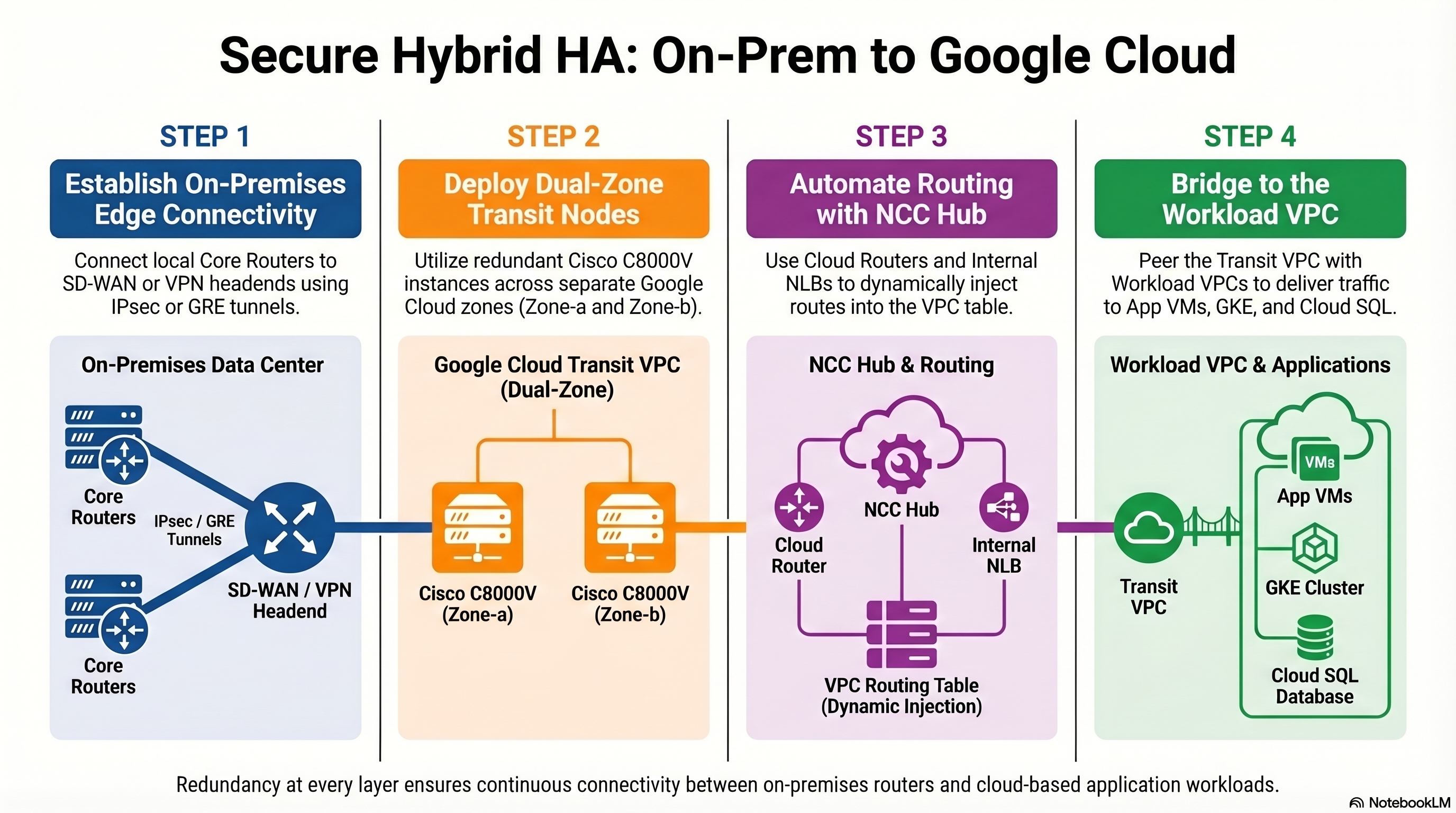
Architecture: One or more C8000V instances deployed as Compute Engine VMs within a dedicated “transit” VPC. The C8000V establishes GRE-over-IPsec tunnels (or native IPsec with VTI) back to on-premises Cisco routers or SD-WAN edge devices. The C8000V runs a full IOS-XE routing stack, participating in the enterprise’s existing IGP/EGP domain. Routes learned from on-premises are injected into the GCP VPC via NCC Router Appliance peering with Cloud Router over eBGP (Google Cloud, 2024a; Cisco Systems, 2024).
What you gain:
- Full IOS-XE feature set: DMVPN (NHRP + mGRE + IPsec), EIGRP, OSPF, MP-BGP with VRF-Lite, PBR, IP SLA, NBAR2/AVC for application visibility, BFD for sub-second failover detection.
- SD-WAN overlay integration: the C8000V can register as a vEdge/cEdge node in vManage, extending the SD-WAN fabric into GCP with centralized policy orchestration, application-aware routing, and SLA-based path selection across multiple WAN transports (Cisco Systems, 2023a).
- Unified operational model: the same NOC team, the same monitoring toolchain (ThousandEyes, vManage, DNA Center), the same change management procedures.
- VRF segmentation within GCP: multiple routing tables on a single C8000V, mapped to different VPCs via multiple vNICs, enabling multi-tenancy without deploying separate appliance instances per tenant.
What you lose:
- VM lifecycle management: patching IOS-XE, right-sizing the Compute Engine instance (minimum
n2-standard-4for production throughput;n2-standard-8recommended for >2 Gbps encrypted throughput), monitoring CPU/memory utilization. - Throughput ceiling bounded by the VM’s vNIC bandwidth cap (up to 32 Gbps on
n2-standard-32, but IPsec encryption overhead reduces effective throughput by 30–50% depending on packet size and cipher suite) (Google Cloud, 2024d). - Complexity of the NCC integration (detailed in Section 5).
Option C: Google Cloud VMware Engine (GCVE) with VMware HCX
Architecture: A GCVE private cloud deployed in a GCP region, running vSphere/vSAN/NSX-T on dedicated bare-metal nodes. VMware HCX provides L2 extension (Network Extension), vMotion (live migration), and bulk migration (HCX Replication Assisted vMotion) between on-premises vSphere and GCVE. The NSX-T overlay provides full L2/L3 network virtualization with microsegmentation (Google Cloud, 2024e).
What you gain:
- True Layer 2 extension: VLAN-backed port groups on-premises can be stretched to GCVE segments, preserving IP addresses, MAC addresses, and broadcast domain membership.
- Workload mobility without re-IP: VMs can vMotion between on-premises and cloud with zero downtime and no IP address change.
- NSX-T distributed firewall for east-west microsegmentation.
What you lose:
- Cost: GCVE private clouds require a minimum three-node cluster of bare-metal hosts. The entry-level configuration (3x
ve1-standard-72nodes) carries a committed monthly spend that dwarfs the cost of a pair of C8000V instances by an order of magnitude. - Operational divergence: GCVE introduces a parallel network control plane (NSX-T) alongside the existing Cisco fabric, creating a bifurcated operational model that requires NSX-T expertise that most Cisco-centric teams do not possess.
- Blast radius: L2 extension via HCX Network Extension carries the risk of broadcast storm propagation from on-premises into the GCVE segment. A misbehaving NIC in the on-premises VLAN can saturate the HCX tunnel and degrade GCVE workloads.
Trade-Off Analysis
| Dimension | Option A: GCP HA VPN | Option B: C8000V (GRE/IPsec) | Option C: GCVE + HCX |
|---|---|---|---|
| Latency (overlay overhead) | Low (native IPsec, no GRE header) | Medium (GRE + IPsec adds 58–62 bytes per packet; TCP MSS clamping required) | Low-Medium (HCX WAN optimization reduces effective latency for bulk transfers) |
| Throughput ceiling | 3 Gbps/tunnel; limited aggregate | VM-bound; 4–10 Gbps realistic with n2-standard-8 and AES-NI | Dedicated bare-metal; 25 Gbps per host NIC |
| Monthly cost (production HA) | ~$150–300/month (tunnels + egress) | ~$800–2,000/month (2x C8000V VMs + BYOL/paygo licensing + egress) | ~$15,000–40,000+/month (3-node minimum GCVE cluster) |
| Operational complexity | Low (managed service) | Medium-High (IOS-XE lifecycle, NCC integration, HA design) | High (vSphere + NSX-T + HCX operational burden) |
| Control plane richness | BGP only | Full IOS-XE: EIGRP, OSPF, MP-BGP, DMVPN, PBR, NBAR2, SD-WAN | NSX-T + BGP (Cloud Router peering via GCVE edge) |
| Unified Cisco management | No (GCP-native console only) | Yes (vManage, DNA Center, ThousandEyes) | No (VMware vCenter/NSX Manager) |
| L2 extension capability | No | No (L3 only; by design) | Yes (HCX Network Extension) |
| Multi-tenancy / VRF | Limited (one Cloud Router per VPC) | Yes (VRF-Lite with per-VRF subinterfaces) | Yes (NSX-T T1 gateways per tenant) |
The trade-off matrix reveals a clear pattern: Option B occupies the optimal position for Cisco-centric enterprises that need advanced traffic engineering, unified management, and cost efficiency without the L2 extension requirement. Option A is appropriate for organizations with simple BGP-based routing needs and no investment in Cisco SD-WAN. Option C is justified only when L2 extension and vMotion-based workload mobility are non-negotiable requirements — a scenario that typically applies to the first 12–18 months of a migration program before applications are re-platformed.
Final Recommendation: Option B — Cisco Catalyst 8000V with NCC Integration
For enterprises operating Cisco routing and SD-WAN infrastructure, the C8000V deployed on GCP Compute Engine, integrated with the Network Connectivity Center (NCC), is the architecturally sound and operationally pragmatic choice.
Data Plane Architecture
The data plane consists of GRE tunnels encapsulated within IPsec transport mode (or, preferably, IPsec tunnel mode with VTI interfaces for simplified QoS and routing configuration). The encapsulation stack, from outer to inner:
| |
This encapsulation adds 66–70 bytes of overhead per packet. For a standard 1500-byte MTU on the GCP VPC (configurable up to 8896 bytes for intra-VPC traffic), the effective Maximum Segment Size (MSS) for TCP traffic traversing the tunnel must be clamped:
| |
On the Tunnel interface:
| |
For SD-WAN overlay integration, the C8000V registers with vManage as a cEdge device, and the IPsec tunnels to on-premises WAN edge nodes are established and orchestrated via the SD-WAN control plane (vBond, vSmart). This eliminates the need for manual tunnel configuration and enables centralized policy-driven path selection (Cisco Systems, 2023a).
Control Plane Architecture — The NCC Imperative
Here is the critical integration point that separates a functional deployment from a production-grade architecture: routes learned by the C8000V from on-premises must be programmatically injected into the GCP VPC routing table. The C8000V, as a user-space VM, has no native mechanism to program Andromeda’s forwarding tables. Static routes in the GCP console pointing to the C8000V’s vNIC are fragile, non-scalable, and operationally unacceptable for any environment with more than a handful of prefixes.
The solution is the Network Connectivity Center (NCC) Router Appliance integration (Google Cloud, 2024a):
Register the C8000V as an NCC Router Appliance spoke. This is performed via the GCP Console or
gcloudCLI, associating the C8000V’s Compute Engine instance and its internal vNIC IP with an NCC Hub.Establish eBGP peering between the C8000V and the Cloud Router. The Cloud Router, which is the NCC Hub’s route reflector and Andromeda control plane ingestion point, peers with the C8000V over an internal eBGP session. The Cloud Router uses ASN 16550 (or a custom private ASN), and the C8000V uses its own private ASN.
1 2 3 4 5 6 7 8 9 10router bgp 65001 bgp router-id 10.10.1.2 bgp log-neighbor-changes neighbor 10.10.1.1 remote-as 65002 neighbor 10.10.1.1 description GCP-CLOUD-ROUTER ! address-family ipv4 unicast network 172.16.0.0 mask 255.255.0.0 neighbor 10.10.1.1 activate exit-address-familyCloud Router propagates learned routes into the VPC. Once the Cloud Router receives prefixes from the C8000V via eBGP, it programs those routes as dynamic custom routes in the VPC routing table via the Andromeda control plane. These routes are then visible to all VMs in the VPC (or in peered VPCs if custom route export is enabled) (Google Cloud, 2024a).
Bidirectional route exchange. The Cloud Router also advertises the VPC’s subnet routes back to the C8000V, which then redistributes them into the on-premises IGP (EIGRP, OSPF) or SD-WAN overlay.
Critical NCC constraint: the eBGP session between the C8000V and Cloud Router must use link-local or RFC 1918 addresses on the same subnet. The C8000V’s internal vNIC IP and the Cloud Router’s peering IP must be in the same VPC subnet. Additionally, the Cloud Router must have the --set-peer-ip-address configured for each BGP peer corresponding to the C8000V’s internal IP (Google Cloud, 2024a).
Topology Summary
Risks and Mitigations
Risk 1: Single Point of Failure
Scenario: A single C8000V instance in one GCP zone represents an unacceptable SPOF. Zone-level maintenance events, live migration failures, or IOS-XE process crashes will sever hybrid connectivity.
Mitigation: Deploy two C8000V instances in separate GCP zones (e.g., us-central1-a and us-central1-b) within the same transit VPC. Both instances peer with the Cloud Router via eBGP, advertising the same on-premises prefixes. Traffic from the workload VPC toward on-premises destinations is directed to the C8000V pair via a GCP Internal Passthrough Network Load Balancer (ILB) configured as the next-hop for on-premises routes.
The ILB performs health checking (TCP or HTTP probe against the C8000V management interface or a custom health endpoint) and removes a failed instance from the forwarding pool within seconds. On the C8000V side, BFD (Bidirectional Forwarding Detection) with sub-second timers ensures rapid eBGP session teardown, causing the Cloud Router to withdraw routes from the failed instance and converge on the surviving peer (Google Cloud, 2024f).
IOS-XE BFD configuration for fast eBGP failover:
| |
Risk 2: MTU / Fragmentation-Induced Performance Degradation
Scenario: GRE + IPsec encapsulation reduces the effective MTU. Applications sending 1500-byte frames will trigger IP fragmentation at the C8000V, causing packet reordering, increased latency, and throughput collapse — particularly devastating for high-throughput database replication (e.g., Oracle Data Guard, SQL Server Always On) and NFS/SMB file transfers.
Mitigation:
- TCP MSS clamping on all tunnel interfaces:
ip tcp adjust-mss 1360. - Path MTU Discovery (PMTUD): Ensure ICMP “Fragmentation Needed” (Type 3, Code 4) messages are not blocked by any firewall in the path. This is a common failure mode in enterprises with overly aggressive ICMP filtering.
- Tunnel MTU configuration: Set
ip mtu 1400on tunnel interfaces. - GCP VPC MTU: Consider configuring the VPC MTU to 1460 (GCP default) or higher if using Jumbo Frames for intra-VPC traffic, but always account for the encapsulation overhead on the tunnel path (Google Cloud, 2024b).
- DF-bit handling: On the C8000V, configure
tunnel path-mtu-discoveryto enable dynamic MTU negotiation for GRE tunnels.
Risk 3: Crypto Performance Bottleneck
Scenario: IPsec encryption/decryption is CPU-intensive. Under-provisioned C8000V instances will hit CPU saturation at moderate throughput levels, causing packet drops and tunnel instability.
Mitigation: Deploy C8000V on n2-standard-8 or larger instance types that expose AES-NI hardware acceleration to the guest OS. IOS-XE automatically leverages AES-NI when available, providing 5–10x improvement in IPsec throughput compared to software-only crypto. Validate with show crypto engine accelerator statistics (Cisco Systems, 2024). Monitor CPU utilization via show processes cpu sorted and GCP Cloud Monitoring; establish alerting thresholds at 70% sustained utilization.
Risk 4: Route Table Explosion and Cloud Router Limits
Scenario: Large enterprise networks may advertise thousands of prefixes from on-premises. Cloud Router has documented limits on the number of learned routes per BGP session and per VPC (Google Cloud, 2024c).
Mitigation: Implement aggressive route summarization on the C8000V before advertising to Cloud Router. Use aggregate-address in BGP to summarize /24s and /25s into /16 or /8 supernets where topologically appropriate. Monitor Cloud Router route counts via gcloud compute routers get-status and set alerting on approach to documented limits.
Real-World Constraints and Organizational Considerations
Legacy Technical Debt: The Re-IP Problem
The single most common blocker to hybrid cloud network modernization is not a technology limitation — it is hardcoded IP addresses embedded in application configurations, database connection strings, firewall rules, load balancer VIPs, and DNS records that have not been updated in years. Changing an application’s IP address in a legacy enterprise is not a network task; it is a cross-functional program requiring application owner sign-off, change advisory board approval, regression testing, and often a maintenance window.
Pragmatic approach: Do not attempt to re-IP applications as part of the initial hybrid connectivity deployment. Instead, design the C8000V overlay to preserve existing IP addressing by advertising the on-premises subnets into GCP with their original CIDR blocks. Cloud-resident applications that need to reach on-premises services will route through the C8000V tunnel transparently. Re-IP efforts should be a separate, application-driven workstream with its own timeline and governance.
Organizational Silos: Network Engineers vs. Cloud Platform Engineers
In most enterprises, the team that manages Cisco routers and SD-WAN infrastructure is not the same team that manages GCP projects, IAM policies, and Terraform modules. The C8000V deployment sits squarely at the intersection of these two domains, and ownership ambiguity will cause operational failures.
Recommendation: Establish a Hybrid Network Ops function — either as a dedicated team or a formal RACI matrix — with clear ownership boundaries:
- Network team owns: IOS-XE configuration, IPsec/GRE tunnel health, routing policy, SD-WAN orchestration, C8000V OS patching.
- Cloud platform team owns: GCP Compute Engine instance lifecycle, VPC network design, Cloud Router / NCC configuration, ILB health checks, IAM permissions, GCP firewall rules.
- Shared responsibility: Capacity planning, throughput monitoring, incident response for connectivity failures.
Infrastructure as Code
The C8000V deployment, NCC configuration, Cloud Router peering, VPC setup, and firewall rules must be codified in Terraform (or Pulumi/OpenTofu). Manual console-click deployments are categorically unacceptable for production hybrid connectivity infrastructure. The Terraform Google provider supports NCC Hub/Spoke resources (google_network_connectivity_hub, google_network_connectivity_spoke), and the C8000V’s IOS-XE configuration can be bootstrapped via Compute Engine metadata startup scripts or day-2 managed via Cisco NSO / Ansible (HashiCorp, 2024).
| |
Licensing
The C8000V on GCP supports two licensing models: BYOL (Bring Your Own License) via Cisco Smart Licensing and PAYG (Pay-As-You-Go) via the GCP Marketplace listing. For enterprises with existing Cisco Enterprise Agreements (EA), BYOL is almost always more cost-effective. Ensure the Smart Licensing satellite or direct cloud connectivity is available from the C8000V’s management interface; a licensing failure will restrict the C8000V to a throughput-limited “evaluation” mode after 90 days (Cisco Systems, 2024).
Conclusion
The C8000V with GCP Network Connectivity Center suits enterprises already invested in Cisco routing and SD-WAN, enabling hybrid cloud connectivity without splitting operational governance. Key benefits include eliminating branch-to-cloud backhaul, 40–60% latency reduction, and unified visibility through vManage, DNA Center, and ThousandEyes — all while working within GCP’s Layer 3 (Andromeda) constraints without the cost of GCVE or limitations of native HA VPN. Successful production deployment hinges on redundancy (dual instances with ILB failover), AES-NI crypto acceleration, proper MTU/MSS handling, and route aggregation discipline. Operational success also depends on Terraform-based infrastructure-as-code, clear RACI boundaries between network and cloud teams, and pragmatic management of technical debt like hardcoded IPs.
TipThe hybrid cloud operating model is permanent. The network architecture must reflect that permanence.
References
Cisco Systems. (2023a). Cisco SD-WAN design guide. Cisco Validated Design. https://www.cisco.com/c/en/us/td/docs/solutions/CVD/SDWAN/cisco-sdwan-design-guide.html
Cisco Systems. (2023b). Cisco SD-WAN cloud onramp for IaaS architecture guide. https://www.cisco.com/c/en/us/td/docs/routers/sdwan/configuration/cloudonramp/ios-xe-17/cloud-onramp-book-xe/cloud-onramp-iaas.html
Cisco Systems. (2024). Cisco Catalyst 8000V Edge Software deployment guide for Google Cloud Platform. https://www.cisco.com/c/en/us/td/docs/routers/C8000V/Configuration/c8000v-installation-configuration-guide.html
Dalton, M., Schultz, D., Agarwal, A., Arbel, Y., Bhatia, A., Gupta, S., Kumar, R., Li, H., McMullen, B., Patil, R., Poutievski, L., & Vahdat, A. (2018). Andromeda: Performance, isolation, and velocity at scale in cloud network virtualization. Proceedings of the 15th USENIX Symposium on Networked Systems Design and Implementation (NSDI ‘18), 373–387. https://www.usenix.org/conference/nsdi18/presentation/dalton
Gartner. (2023). Top strategic technology trends for 2024. Gartner, Inc. https://www.gartner.com/en/articles/gartner-top-10-strategic-technology-trends-for-2024
Google Cloud. (2024a). Network Connectivity Center overview. Google Cloud Documentation. https://cloud.google.com/network-connectivity/docs/network-connectivity-center/concepts/overview
Google Cloud. (2024b). VPC network overview. Google Cloud Documentation. https://cloud.google.com/vpc/docs/vpc
Google Cloud. (2024c). Cloud VPN overview and quotas. Google Cloud Documentation. https://cloud.google.com/network-connectivity/docs/vpn/concepts/overview
Google Cloud. (2024d). Compute Engine machine types and network bandwidth. Google Cloud Documentation. https://cloud.google.com/compute/docs/machine-types
Google Cloud. (2024e). Google Cloud VMware Engine overview. Google Cloud Documentation. https://cloud.google.com/vmware-engine/docs/overview
Google Cloud. (2024f). Internal passthrough Network Load Balancer overview. Google Cloud Documentation. https://cloud.google.com/load-balancing/docs/internal
HashiCorp. (2024). Google Cloud provider: Network Connectivity Center resources. Terraform Registry. https://registry.terraform.io/providers/hashicorp/google/latest/docs
Dantas, R. N. (2024). terraform-c8000v-gcp: Production Terraform modules for Cisco C8000V hybrid connectivity on Google Cloud Platform [Open-source software]. GitHub. https://github.com/ronaldonascimentodantas/terraform-c8000v-gcp